If you seek comprehensive information about AC motors, you’ve come to the right place. Custom AC motors fall into two main categories: synchronous and asynchronous. The most common type of asynchronous motor is the AC induction motor, which custom motor manufacturers make using an AC transformer with a rotating secondary. In this type of motor, the primary winding, or stator, connects to the power source while the shorted secondary member, or rotor, carries the induced secondary current. The action of rotor currents on the air-gap flux produces torque. An asynchronous motor, on the other hand, is in a separate AC motor class because of the differences in design and operational characteristics. Sinotech offers a robust catalog of motors made by our AC motor manufacturers that can be tailored to your exact specifications.
Discover the latest about AC motors on our blog.
Asynchronous VS Synchronous AC Motrs
Asynchronous Induction AC Motors Overview
Asynchronous AC Motors
All induction motors are asynchronous motors. As one of the simplest, most rugged electric motors, AC induction motors have two basic electrical assemblies: a wound stator and rotor assembly. The motor derives its name from the currents flowing into the rotor, which alternating currents flowing in the primary member, or stator, induce. The combined magnetic effects of stator and rotor currents produce the force needed to create a rotation.
AC motors, including, AC induction motors, have rotors with laminated, cylindrical iron cores with slots for receiving conductors. The most common type of rotor made by AC motor manufacturers is sometimes referred to as a “squirrel cage,” which has cast-aluminum conductors and short-circuiting end rings. The squirrel cage rotates when the moving magnetic field creates a current in the shortened conductors.
In an AC motor, the speed at which the magnetic field rotates is referred to as the synchronous speed (ns). This speed is determined by the number of poles in the stator and the power supply’s frequency. The formula to calculate an AC motor’s synchronous speed is ns = 120f/p.
- ns: synchronous speed in rpm
- f: line voltage frequency in Hz
- p: number of poles
Synchronous speed is the absolute upper limit of an AC motor’s speed. If a rotor turns exactly as fast as the rotating magnetic field, the rotor conductors cut no lines of force and produces no torque.
As an AC motor runs, the rotor always rotates slower than the magnetic field. The rotor’s speed is just slow enough to cause the proper amount of rotor current flow to allow the resulting torque to be sufficient enough to drive the load and overcome windage and friction losses.
The speed difference between an AC motor’s rotor and magnetic field is referred to as “slip.” Slip is the percentage of synchronous speed. The formula to calculate slip is s = 100 (ns – na)/ns.
- s = slip
- ns = synchronous speed
- na = actual speed
Synchronous Motors Overview
Synchronous motors have a special rotor construction that allows them to rotate at the same speed as the stator field. In other words, they operate in absolute synchronism with line frequency. The major types of synchronous motors include nonexcited and direct-current-excited motors. Similar to induction AC motors, the speed of synchronous motors is determined by the number of pairs of poles. It’s calculated by the ratio of the line frequency.
Custom motor manufacturers design synchronous motors in a range of sizes, from subfractional self-excited units to large-horsepower, direct-current-excited AC motors for industrial drives. In the fractional-horsepower range, synchronous motors serve to provide precise constant speed.
When applied to industrial loads, synchronous motors with large horsepower ratings serve two important functions:
- Provide a highly efficient means of converting AC energy into mechanical power
- Operate at leading or unity power factor, thus providing power-factor correction
Synchronous Non-Excited Electric Motors
AC motor manufacturers create nonexcited electric motors using reluctance and hysteresis designs. They use a self-starting circuit and require no external excitation supply.
Synchronous Direct-Current-Excited Electric Motors
DC-excited electric motors are available in sizes larger than 1 hp. To operate, they require a direct current supplied through slip rings for excitation. The motor receives a direct current from a separate source or a DC generator connected to the AC motor shaft.
Single-phase and polyphase synchronous motors must be driven or have their rotor connected in the form of a self-starting circuit in order to start. Because the electric motor field rotates at a synchronous speed, the electric motor must be accelerated before it can pull into synchronism. Accelerating from zero speed requires slip until achieving synchronism. Consequently, it’s important to employ a separate means to start.
In self-starting electric custom AC motor designs, fhp sizes use starting methods common to induction electric motors, such as split-phase, capacitor-start, repulsion-start, and shaded-pole. The motors automatically switch to synchronous operation because of the electrical characteristics.
DC-excited motors use a squirrel cage called an amortisseur or damper winding to start. Incidentally, the motor’s inherent low starting torque and need for a DC power source require a starting system that:
- Provides full electric motor protection while starting
- Applies DC field excitation at the proper time
- Removes field excitation at rotor pull out (maximum torque)
- Protects the electric motor’s squirrel-cage winding against thermal damage during out-of-step conditions
A Look at Torque in Direct-Current-Excited Electric Motors
Pull-Up Torque
An electric motor’s pull-up torque is defined as the minimum torque created from a standstill to the pull-in point. This torque must exceed the load torque enough to maintain a satisfactory acceleration rate under normal voltage conditions.
Reluctance Torque
A motor’s reluctance torque is the result of the rotor pole pieces’ saliency, which is the preferred direction of magnetization. It pulsates at speeds below synchronous.
Reluctance torque influences the motor’s pull-in and pull-out torques as the unexcited salient-pole rotor tends to align with the stator electric motor’s magnetic field to maintain minimum magnetic reluctance. An electric motor’s reluctance may be enough to pull a lightly loaded, low-inertia system into synchronism and develop a pull-out torque of approximately 30 percent.
Synchronous Torque
An electric motor’s synchronous torque is the torque created after the application of excitation. It represents the total steady-state toque available to drive a load. The torque maxes out at about 70 lag of the rotor behind the rotating stator magnetic field. The maximum value, however, is the pull-out torque.
Pull-Out Torque
Pull-out torque is the maximum sustained torque an electric motor develops at a synchronous speed for one minute with rated frequency and normal excitation. Normal pull-out torque is typically 150 percent of full-load torque for unity-power-factor electric motors. It’s 175 to 200 percent for 0.8-leading-power-factor electric motors.
Pull-In Torque
A synchronous motor’s pull-in torque is the torque developed when pulling the connected inertia load into synchronism upon the application of excitation. It’s developed during the transition from slip speed to synchronous speed, as electric motors change from induction to synchronous operation. This tends to be the most critical period when starting a synchronous motor. At synchronous speed, the torque developed by the amortisseur and field windings becomes zero. As a result, only the reluctance and synchronizing torque provided by exciting the field windings are effective at the pull-in point.
Additional Custom AC Motor Design Types
Polyphase AC Motors
Polyphase squirrel-cage AC motors, such as three-phase motors, are constant-speed machines. They have some degree of flexibility in operating characteristics when modifying the rotor slot design. Variations in AC motors produce changes in current, torque and full-load speed. Standardization and innovation have produced four fundamental types of AC motors:
Designs A and B Characteristics
- General-purpose AC motor with normal starting torques and currents, as well as low slip
- Fractional polyphase AC motors are generally design B
- Because design B has drooping characteristics, a polyphase AC motor with the same breakdown, or maximum, torque as a single-phase AC motor can’t attain the same speed-torque point for a full-load speed as single-phase custom AC motor designs
- Breakdown torque must be higher for comparable full-load speeds (a minimum of 140 percent of the breakdown torque of single-phase, general-purpose AC motors)
Design C Characteristics
- High starting torque with a normal starting current and low slip
- Used where breakaway loads are high at starting, but normally run at the rated full load
- Not subject to high overload demands after reaching the running speed
Design D Characteristics
- High slip that allows speed to drop when encountering fluctuating loads
- Low starting current
- Low full-load speed
- This design can be divided into several sub-groups that vary by slip or the shape of the speed-torque curve
Design F Characteristics
- Low starting torque
- Low starting current
- Low slip
- Custom motor manufacturers build the AC motors to obtain low locked-rotor current
- Locked-rotor and breakdown torque are low
- The motors are generally used when the starting torque is low and high overloads aren’t imposed after reaching the running speed
Wound-Rotor AC Motors
Squirrel-cage AC motors are relatively inflexible in regard to speed and torque characteristics. A special wound-rotor AC motor, however, has controllable speed and torque. The applications of wound-rotor AC motors are markedly different from squirrel-cage AC motors because of the rotor circuit’s accessibility. Obtaining the AC motor’s performance characteristic is a matter of inserting different resistance values in the rotor circuit.
A secondary resistance in the rotor circuit generally starts wound-rotor AC motors. The AC motor’s resistance is then sequentially reduced to allow the motor to come up to speed. As a result, AC motors can develop significant torque while limiting the locked-rotor current. AC motor manufacturers can design this secondary motor resistance for continuous service to dissipate the heat produced by continuous operation at reduced speeds, frequent acceleration, or acceleration with large inertia loads.
External resistance gives AC motors a characteristic that results in large drops in rpm for a small change in load. Reduced AC motor speed is provided down to about 50 percent rated speed, but efficiency remains low.
Multi-Speed AC Motors
Custom motor manufacturers design consequent-pole AC motors to operate at one speed. By physically reconnecting the leads, they can achieve a 2:1 speed ratio. Typical speeds for 60-Hz AC motors are:
- 3,600/1,800 rpm (2/4 pole)
- 1,800/900 rpm (4/8 pole)
- 1,200/600 rpm (6/12 pole)
Two-winding AC motors have two individual windings that manufacturers can wind for any number of poles to facilitate obtaining other speed ratios. Ratios greater than 1:4, however, are impractical because of an AC motor’s size and weight. Single-phase AC motors generally have a variable-torque design. However, constant-torque and constant-horsepower AC motors are also available.
The power output of AC motors can be proportioned to each different speed. Such custom AC motor designs have output horsepower capacity in accordance with one of the following load characteristics:
- Variable torque: These AC motors have speed-torque characteristics that vary with the square of the speed. For instance, a 1,800/900-rpm electrical motor that develops 10 hp at 1,800 rpm produces 2.5 hp at 900 rpm. Because AC motors face loads—such as centrifugal pumps, fans and blowers—their torque requirement vary with the square or cube of the speed. This motor characteristic is generally adequate.
- Constant torque: These AC motors can develop the same torque at each speed. As a result, the power output varies directly with speed. For example, an AC motor rated at 10 hp at 1,800 rpm produces 5 hp at 900 rpm. You’ll find these motors in applications with constant torque requirements, such as mixers, conveyors and compressors.
- Constant horsepower: These AC motors develop the same horsepower at each speed. Torque is inversely proportional to speed. Applications for such AC motors include machine tools, including drills, milling machines and lathes.
Single-Phase AC Motors
Single-phase induction AC electric motors are commonly fractional-horsepower types. However, single-phase integral-horsepower is available in the lower horsepower range. The most common fractional-horsepower single-phase AC motors are:
- Split-phase
- Capacitor-smart
- Permanent split-capacitor
- Shaded pole
This custom AC motor design is available in multi-speed types, but there are practical limits to the number of speeds obtained. Those with two-, three- and four-speed motors are available. Consequent-pole or two-winding methods may accompany speed selection.
Universal Motors
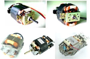
Universal Motors
Universal motors operate with nearly equivalent performance on direct or alternating currents up to 60 Hz. AC motors differ from DC motors because of their winding ratios and thinner iron laminations. DC motors can run on an alternating current, but with poor efficiency. Universal motors may operate on a direct current with an essentially equivalent AC motor performance. However, they have poorer commutation and brush life compared to an equivalent DC motor. An important characteristic of universal AC motors is they have the highest horsepower-per-pound ratio of any AC motor because they operate at speeds many times higher than that of any 60-Hz electric motor.
When operated without a load, universal motors tend to run away. Speed is limited only by windage, friction and commutation. Therefore, large universal motors are almost always connected directly to the load to limit speed. On portable tools, such as electric saws, the load imposed by the gears, bearings and cooling fan is enough to hold the no-load speed down to a safe value.
With a universal motor, speed control is simple because the electric motor speed is sensitive to voltage and flux changes. A rheostat or adjustable autotransformer allows the AC motor’s speed to be readily varied from top speed to zero.
Timing Electric Motors
Timing electric motors are rated under 1/10 hp and are used as the prime movers for timing devices. Because the motor is used as a timer, it must run at a constant speed.
AC and DC electric motors may be used as timing motors. DC electric timing motors serve portable applications or when high acceleration and low speed variations are required. While some form of mechanical or electrical speed governor is required, such electric motors offer advantages, including:
- 50 to 70 percent efficiency
- Starting torque as high as 10 times the running torque
- Relatively easy speed control
AC Servo Motors
Servo motors are used in AC servomechanisms and computers that require rapid, accurate response characteristics. To obtain these characteristics, servo motors have small-diameter, high-resistance rotors. The smaller diameter provides low inertia for fast starts, stops and reversals. The high resistance allows for a nearly linear speed-torque relationship for accurate control.
Custom motor manufacturers wind servo motors with two phases physically at right angles or in-space quadrature. The motors feature a fixed or reference winding that’s excited from a fixed voltage source. The control winding is excited by an adjustable or variable control voltage, usually from a servoamplifier. Engineers design servo motor windings with the same voltage-turn ratio so the power inputs at maximum fixed-phased excitation and the maximum control-phase signal are balanced.
In an ideal servo motor, torque at any speed is directly proportional to the motor’s control-winding voltage. However, this relationship only exists at zero speed because of the inherent inability of an induction servo motor to respond to voltage input changes under light load conditions.
The inherent damping of servo motors decrease as ratings increase, and the motors have a reasonable efficiency at the sacrifice of speed-torque linearity. Many larger servo motors have integral auxiliary blowers to maintain temperatures within safe operating ranges. AC servo motors are available in power ratings from less than 1 to 750 W, in sizes ranging from 0.5- to 0.7-inch OD. Most AC servo motors are with modular or built-in gearheads.
Interested in AC linear motors? Read about their history, characteristics and applications here.
Sinotech engineers custom AC motors in the U.S. and manufactures them in several locations throughout Pacific Rim to keep your costs and risks low. Contact us today and let us know how our custom AC motor manufacturing services can get your application up and running today.