Wide World of Custom Motor Shafts: Stepped, Splined, Helical, and Threaded
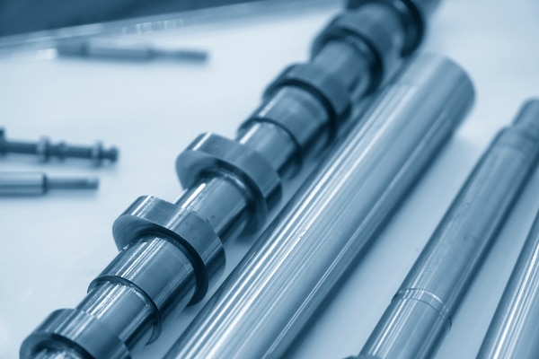
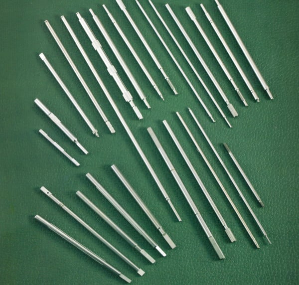
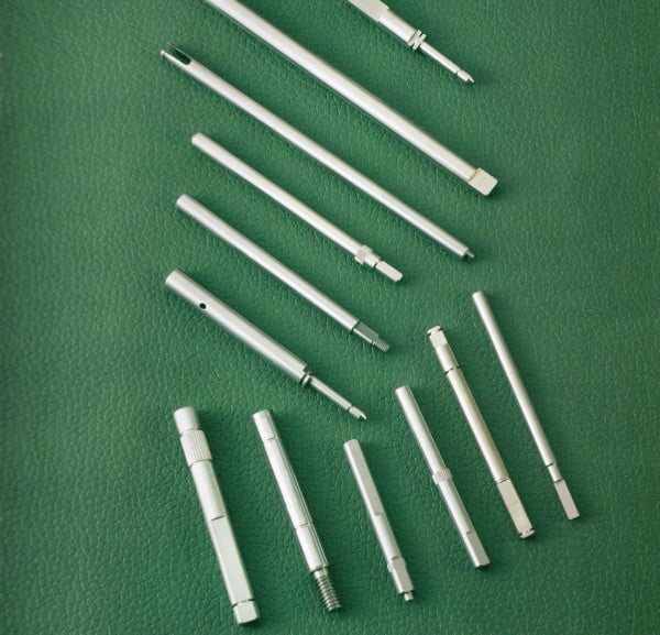
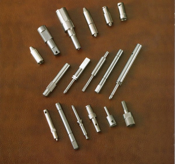
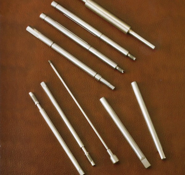
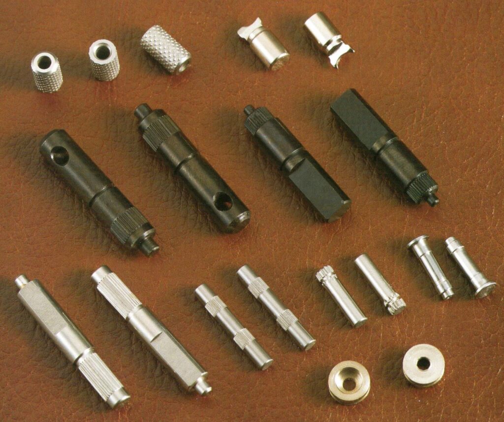
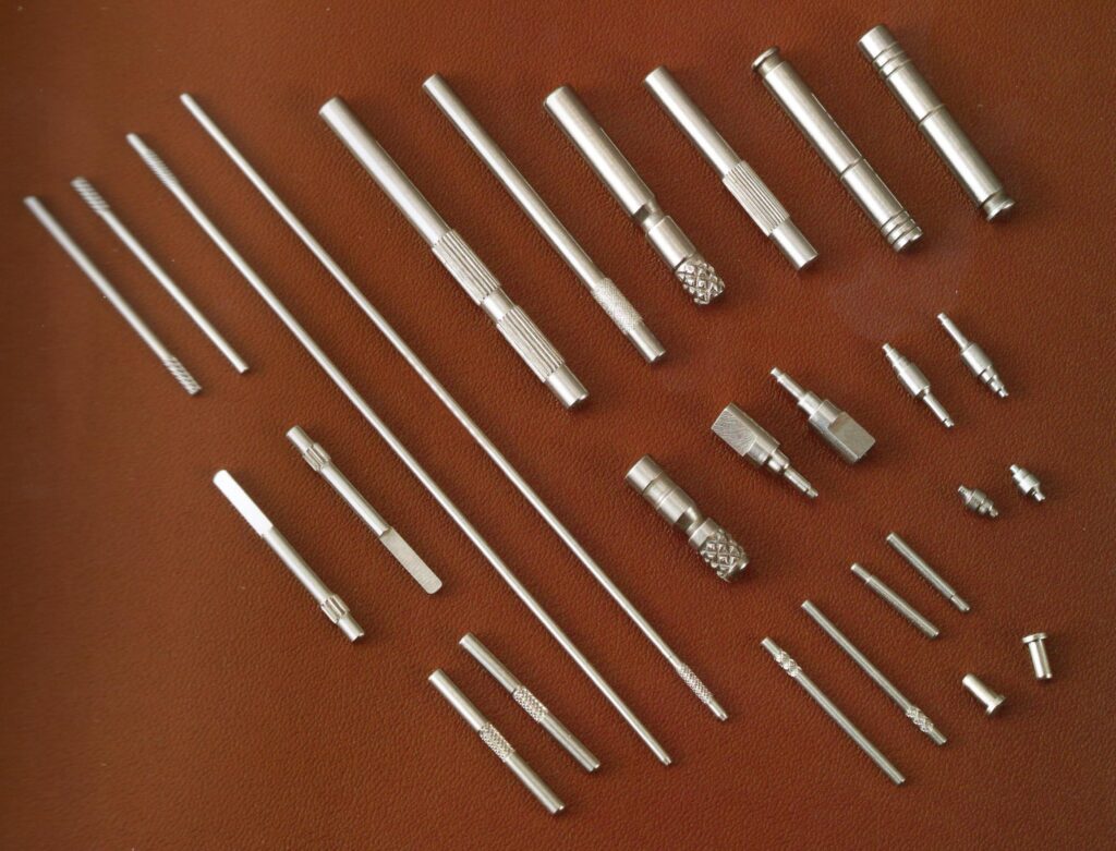
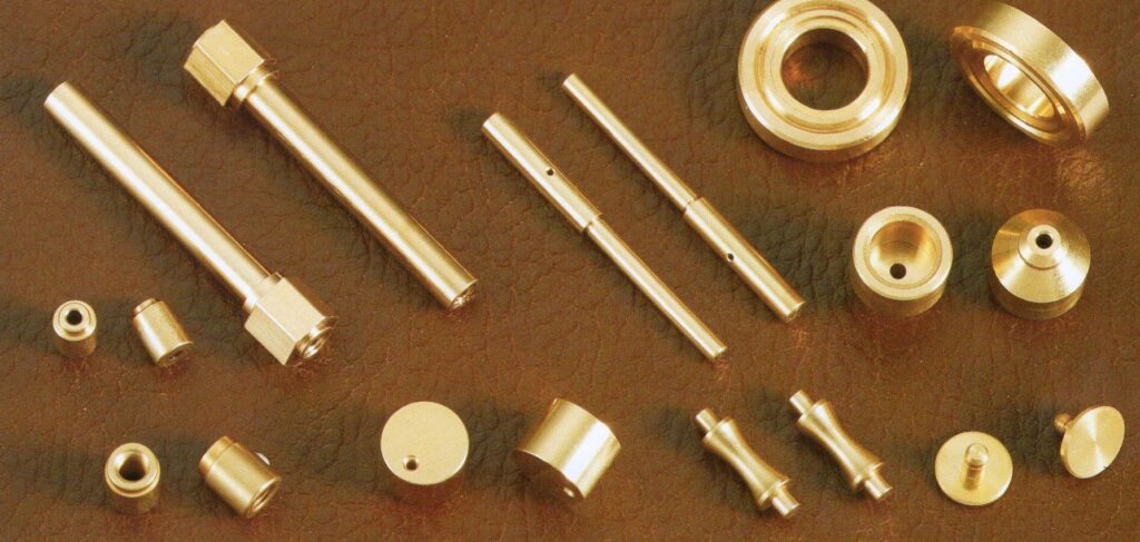
Sinotech can produce a wide range of custom shafts for every application including motor shafts, industrial and automotive applications. These include round shafts, square shafts, stepped shafts, splined shafts, helical shafts, gear shafts, D-key shafts, and threaded shafts.
Bring us your ideas and we’ll help you get your shaft application of the ground. Learn about our products:
Sinotech has audited, qualified and worked with QS-9000 and ISO certified shaft factories in the Pacific Rim for over 15 years. We are dedicated to managing your custom shaft project on-site and delivering parts to you at lower prices but the same quality as a domestic supplier.
Overview of Custom Shaft Offerings
Sinotech produces a wide variety of shafts:
- Custom shafts
- Round cross-section
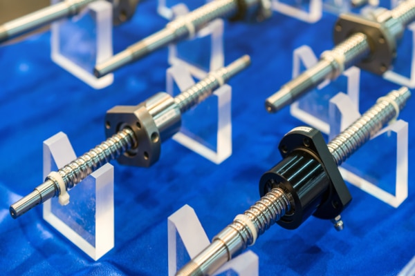
- Splined Shafts
- Square/rectangular
- Cam Shafts
- D-shaped key end
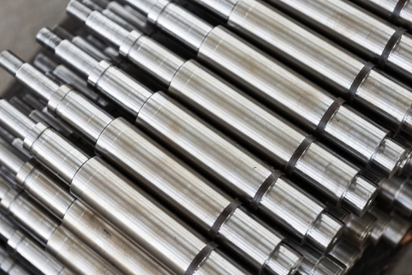
- Stepped Shafts
- Slotted end
- Helical Shafts
- Geared Shafts
There is an ISO standard for shafts ISO 496:1973.
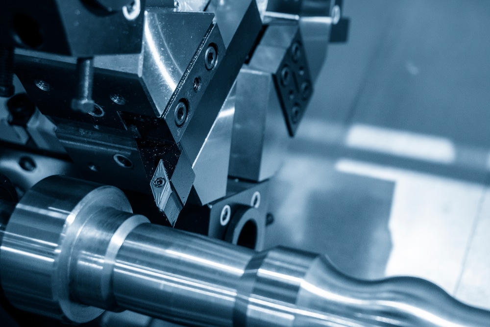
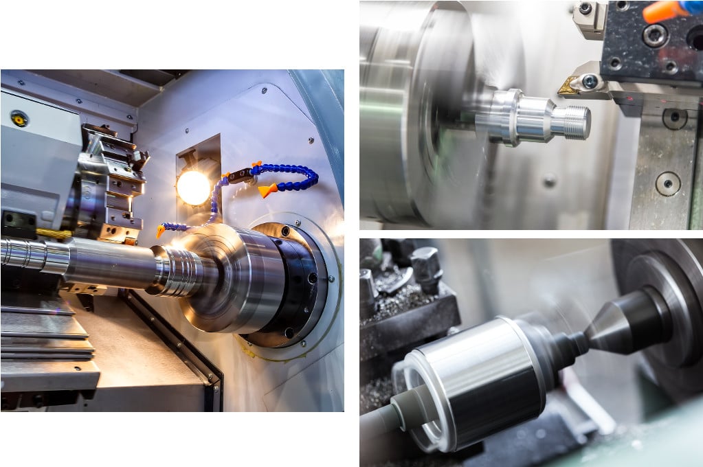
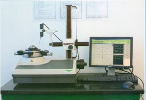
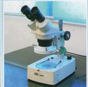
Equipment and Processes for Manufacturing Custom Shafts
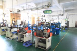
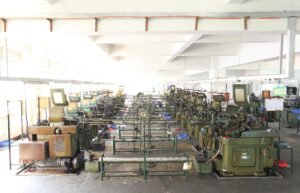
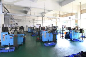
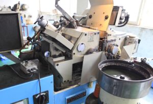
Sinotech brings together advanced manufacturing equipment such as CNC and lathes from Japan and Taiwanese centerless grinding machines, gear hobbing machines, straightening and cutting machines, sphere lapping machines, end grinders, cylindrical grinders, rolling grinders, and ultrasonic cleaning and polishing machines. These are key to manufacturing custom shafts and motor shafts.
Custom Shaft Production Machinery
| Precision Grinder | SUPERFINA | Surface Grinder |
OKAMOTO |
| Gear Hobbing Machine |
KITAL SANGYO KOEPFER |
Ball Surface Grinder |
TOKYO |
| Digital Controlled Non-core grader |
NISSIN | Rolling Grinder |
JAGURA |
| Non-core Grinder | NISSIN SHINKO OHMIKY |
Raw Material Cutter |
TOKYO /CHNG YU |
| Automatic Lathe | TSUGAMI |
Punching Machine |
JAHASHIMA |
| CNC Lathe | TSUGAMI | Round Grinder |
SINKO |
| Computerized Milling Machine |
BRIDGEPORT | Pattern Twining Machine |
SUNAC |
| Two-time Processing Machine |
TSUGAMI | Ultrasonic Cleaning Machine |
COLD |
Shaft Production Workshop

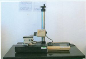
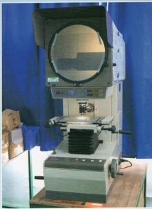
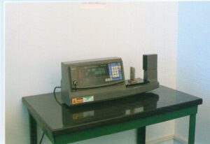
Quality Control Systems for Custom Shafts and Motor Shafts
High precision manufacturing and laboratory test equipment provides for consistency and accuracy of standard and custom shafts.
Quality Systems for Custom Shafts
ISO9001:2008
ISO/TS 16949:2009
We are experts in providing Level 3 PPAP documentation for custom shafts and motor shafts, including:
- Capability studies
- Control plans
- Gage R&Rs
- Failure Modes and Effects Analysis (FMEA)
- Custom statistical analysis

Related Sinotech Products Related to Custom Shafts
Sinotech’s custom shafts abound in electric motors. If you purchase motors, or motor components, you might want to review these related Sinotech products.
- Electric motor catalog
- Armatures and field coils
- Commutators
- Laminations
- Magnets
- Motor brushes
- Wound coils
Custom Motor Shaft Materials
Motor shafts are a key component in most rotating equipment. When considering the best material for your electric motor shaft, there are several considerations: Cost and Material Deficiencies.
Materials in common use
Most motor manufacturers use SAE 1045 in either cold-rolled (CRS) or hot-rolled steel (HRS). C1045 is a medium carbon, medium tensile steel supplied as forged or normalized. This steel shows good strength, toughness and wear resistance.
It is used for axles, bolts, forged connecting rods, crankshafts, torsion bars, light gears, guide rods; but, especially, motor shafts.
Other materials include sulfurized SAE 1117, SAE 1137, SAE 1144, hot-rolled SAE 1035, and cold-rolled SAE 1018. A ground stock of any material is used on special CNC Swiss turning machines.
Cold-rolled and sulfurized steels
Generally, the cold-rolled and sulfurized steels will increase costs approximately 15% more than HRS and will machine better. Machining trials need to be performed in order to justify the extra cost. Since all shaft-turning machines perform differently, there is no established material or machining practice.
The hot-rolled plain carbon steel, on a cost-per-pound basis, is cheaper than cold-rolled sulfurized steel. But there are trade offs. The hot-rolled material has to be sized larger than cold-rolled because of the lack of outer diameter (OD) control in the rolling process.
Materials used for motor shafts
Manufacturers of electric motors evaluate whether the larger-size and lower-material-cost hot-rolled bar stock for motor shafts is more or less costly than cold-rolled bar stock.
The hot-rolled material, by the very nature of its processing, has hard and soft spots, residual stresses, voids, and other material deficiencies, making it more difficult to machine. The problem with some high strength steels is the hardest part is only the outside layers, so when the shaft is machined down you will lose the strength.
Machine trials needed
Machine trials need to be conducted to decide the best option between CRS, HRS, non-sulfurized, and sulfurized motor shafts. Due to the difficulties with HRS, most motor manufacturers use sulfurized CRS.
Sinotech produces camshafts, like many custom shafts, can be difficult to manufacture due to their complex geometry.
The camshaft came to Turkey in 1206 by Al-Jazari. He employed it as part of his automata, water-raising machines, and water clocks such as the castle clock. Camshafts later appeared in European mechanisms from the 14th century.
Among the first car with single overhead camshaft engine is the Maudslay by Alexander Craig and introduced in 1902. Another is the Marr Auto Car by Michigan native Walter Lorenzo Marr in 1903.
In internal combustion engines with pistons, the camshaft operates poppet valves. It consists of a cylindrical rod running the length of the cylinder bank with a number of oblong lobes protruding from it, one for each valve. Cam lobes force the valves open by pressing on the valve, or on some intermediate mechanism, as they rotate.
Motor Shaft Materials
Camshafts are made out of several types of material. These include:
Chilled iron castings
Commonly used in high volume production, chilled iron camshafts have good wear resistance since the chilling process hardens them. Other elements added to the iron before casting make the material more suitable for its application.
Billet steel
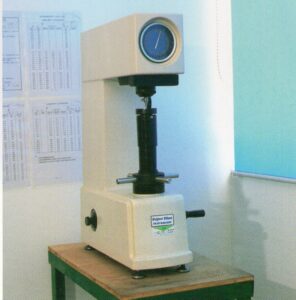
High quality camshaft or low volume production requires, engine builders and camshaft manufacturers to choose steel billet. This is a much more time consuming process, and is generally more expensive than other methods. However, the finished product is far superior. CNC lathes, CNC milling machines, and CNC camshaft grinders may be used during production. Different types of steel bar are used, one example is EN40b. A camshaft manufactured from EN40b is also heat treaded via gas nitriding. This changes the micro-structure of the material. It provides a surface hardness of 55-60 on the Rockwell Hardness Scale. These types of camshafts are used in high-performance engines.
Camshaft Timing for Motor Shafts
The relationship between the rotation of the camshaft and the rotation of the crankshaft is of critical importance. Since the valves control the flow of the air/fuel mixture intake and exhaust gases, they must be opened and closed at the appropriate time during the stroke of the piston. For this reason, the camshaft is connected to the crankshaft, a motor shaft, either directly, via a gear mechanism, or indirectly via a belt or chain called a timing belt or timing chain. Direct drive using gears is unusual because of the cost. The frequently reversing torque caused by the slope of the cams tends to cause gear rattle which for an all-metal gear train requires further expense of a cam damper.
Fiber gears
Rolls-Royce V8 (1954) used gear drive as, unlike chain, it could be made silent and to last the life of the engine. Where gears are used in cheaper cars, they tend to be made from resilient fiber rather than metal, except in racing engines that have a high maintenance routine. Fiber gears have a short life span and must be replaced regularly, much like a timing belt. In some designs the camshaft also drives the distributor and the oil and fuel pumps. Some vehicles may have the power steering pump driven by the camshaft. With some early fuel injection systems, cams on the camshaft operated the fuel injectors. Honda redesigned the VF750 motorcycle from chain drive to the gear drive VFR750 due to insurmountable problems with the VF750 Hi-Vo inverted chain drive.
Beveled gears
An alternative used in the early days of overhead cam (OHC) engines was to drive the camshaft(s) via a vertical shaft with bevel gears at each end. This system was used on the pre-World War I Peugeot and Mercedes Grand Prix cars. Another option was to use a triple eccentric with connecting rods; these were used on certain W.O. Bentley-designed engines and also on the Leyland Eight.
Two-stroke/four-stroke engines
In a two-stroke engine that uses a camshaft, each valve is opened once for every rotation of the crankshaft; in these engines, the camshaft rotates at the same speed as the crankshaft. With four-stroke engines, the valves are opened only half as often; thus, two full rotations of the crankshaft occur for each rotation of the camshaft.
The timing of the camshaft can be advanced to produce better low RPM torque, or retarded for better high RPM power. Changing cam timing moves the overall power produced by the engine down or up the RPM scale. The amount of change is very little (usually < 5 deg), and affects valve to piston clearances.
Motor Shaft (Camshaft) Duration
Duration is the number of crankshaft degrees of engine rotation during which the valve is off the seat. In general, greater duration results in more horsepower. The RPM at which peak horsepower occurs is typically increased as duration increases at the expense of lower rpm efficiency (torque).
Power and idle characteristics
Duration specifications can often be misleading because manufacturers may select any lift point from which to advertise a camshaft’s duration and sometimes will manipulate these numbers. The power and idle characteristics of a camshaft rated at a .006″ lift point will be much different from one with the same rating at a .002″ lift point.
Many performance engine builders gauge a race profile’s aggressiveness by looking at the duration at .020″, .050″ and .200″. The .020″ number determines how responsive the motor will be and how much low end torque the motor will make. The .050″ number is used to estimate where peak power will occur, and the .200″ number gives an estimate of the power potential.
Increased overlap in motor shaft duration
A secondary effect of increased duration can be increased overlap, which is the number of crankshaft degrees during which both intake and exhaust valves are off their seats. It is overlap which most affects idle quality, inasmuch as the “blow-through” of the intake charge immediately back out thru the exhaust valve which occurs during overlap reduces engine efficiency, and is greatest during low RPM operation. In general, increasing a camshaft’s duration typically increases the overlap, unless the intake and exhaust lobe centers are moved apart to compensate.
Motor shaft (Camshaft) Lift
The camshaft “lift” is the resultant net rise of the valve from its seat. The farther the valve rises from its seat the more airflow can be provided, which is generally more beneficial. Greater lift has some limitations. First, lift is limited by the increased proximity of the valve head to the piston crown and secondly, greater effort is required to move the valve springs to a higher state of compression. Increased lift can also be limited by lobe clearance in the cylinder head casting. Higher valve lift can have the same effect as increased duration where valve overlap is less desirable.
When lift is too high
More lift allows greater airflow; although even by allowing a larger volume of air to pass thru the larger opening, the brevity of the typical duration with a higher lift cam results in less airflow than with a cam with lower lift but more duration, all else being equal. On forced induction motors this higher lift could yield better results than longer duration, particularly on the intake side. Notably though, higher lift has more potential problems than increased duration, in particular as valve train rpm rises which can result in less efficient running or loss of torque.
Excessive valve lift
Cams that have excessive valve lift, running at high rpm, can cause what is called “valve float”, where the valve spring tension is insufficient to keep the valve following the cam at its apex. This could also be a result of a very steep rise of the lobe, where the valve is effectively shot off the end of the cam rather than following the cams’ profile. This is typically what happens when a motor over revs: when the engine rpm exceeds the maximum design rpm. The valve train is typically the limiting factor in determining the maximum rpm the engine can maintain either for a prolonged period or temporarily. Sometimes an over rev can cause engine failure when the valves become bent as a result of colliding with the piston crowns.
Position
Depending on the location of the camshaft, the cam operates the valves either directly or through a linkage of pushrods and rockers. However, direct operation involves a simpler mechanism and leads to fewer failures, but requires the camshaft to be positioned at the top of the cylinders. As In the past, when engines were not as reliable as today, this was seen as too much trouble. But in modern gasoline engines the overhead cam system, where the camshaft is on top of the cylinder head, is quite common.
Number of camshafts
While today some engines rely on a single camshaft per cylinder bank, which is known as a single overhead camshaft (SOHC), most modern engines are driven by a two camshafts per cylinder bank arrangement (one camshaft for the intake valves and another for the exhaust valves); such camshaft arrangement is known as a double or dual overhead cam (DOHC), thus, a V engine, which has two separate cylinder banks, may have four camshafts (colloquially known as a quad-cam engine).
The modern W engine
More unusual is the modern W engine (also known as a ‘VV’ engine to distinguish itself from the pre-war W engines) that has four cylinder banks arranged in a “W” pattern with two pairs narrowly arranged with a 15-degree separation. Even when there are four cylinder banks (that would normally require a total of eight individual camshafts), the narrow-angle design allows the use of just four camshafts in total. For the Bugatti Veyron, which has a 16-cylinder W engine configuration, the four camshafts are driving a total of 64 valves.
The overhead camshaft design adds more valvetrain components that ultimately result in more complexity and higher manufacturing costs, but this is easily offset by many advantages over the older design: multi-valve design, higher RPM limit, and design freedom to better place valves, spark plugs, and intake/exhaust ports.