Shaded Pole Motors
Shaded pole motors are probably the simplest and most rugged of all electric motors. They consist of two basic electrical assemblies: the wound stator and the rotor assembly.
The rotor consists of laminated, cylindrical iron cores with slots for receiving the conductors. On early motors, the conductors were copper bars with ends welded to copper rings known as end rings. Viewed from the end, the rotor assembly resembles a squirrel cage, hence the name squirrel- cage motor is used to refer to induction motors. In modern induction motors, the most common type of rotor has cast-aluminum conductors and short-circuiting end rings. The rotor turns when the moving magnetic field induces a current in the shorted conductors. The speed at which the magnetic field rotates is the synchronous speed of the motor and is determined by the number of poles in the stator and the frequency of the power supply.
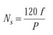
Where:
Ns = synchronous speed
f = frequency
P = number of poles
Synchronous speed is the absolute upper limit of motor speed. At synchronous speed, there is no difference between rotor speed and rotating field speed, so no voltage is induced in the rotor bars, hence no torque is developed. Therefore, when running, the rotor must rotate slower than the magnetic field. The rotor speed is just slow enough to cause the proper amount of rotor current to flow, so that the resulting torque is sufficient to overcome windage and friction losses, and drive the load. This speed difference between the rotor and magnetic field, called slip, is normally referred to as a percentage of synchronous speed:
| s= | 100(Ns-Na) |
| Ns |
Where:
s = slip
Ns = synchronous speed
Na = actual speed
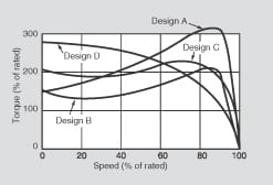
Figure 1 – Typical speed-torque characteristics for Design A, B, C, and D motors.
Polyphase Motors
NEMA classifies polyphase induction motors according to locked rotor torque and current, breakdown torque, pull up torque, and percent slip.
- Locked rotor torque is the minimum torque that the motor develops at rest for all angular positions of the rotor at rated voltage and frequency.
- Locked rotor current is the steady state current from the line at rated voltage and frequency with the rotor locked.
- Breakdown torque is the maximum torque that the motor develops at rated voltage and frequency, without an abrupt drop in speed.
- Pull up torque is the minimum torque developed during the period of acceleration from rest to the speed that breakdown torque occurs. Figure 1 illustrates typical speedtorque curves for NEMA Design A, B, C, and D motors.
- Design A motors have a higher breakdown torque than Design B motors and are usually designed for a specific use. Slip is 5%, or less.
- Design B motors account for most of the induction motors sold. Often referred to as general purpose motors, slip is 5% or less.
- Design C motors have high starting torque with normal starting current and low slip. This design is normally used where breakaway loads are high at starting, but normally run at rated full load, and are not subject to high overload demands after running speed has been reached. Slip is 5% or less.
- Design D motors exhibit high slip (5 to 13%), very high starting torque, low starting current, and low full load speed. Because of high slip, speed can drop when fluctuating loads are encountered. This design is subdivided into several groups that vary according to slip or the shape of the speed-torque curve. These motors are usually available only on a special order basis.
Wound-rotor Motors
Although the squirrel-cage induction motor is relatively inflexible with regard to speed and torque characteristics, a special wound-rotor version has controllable speed and torque. Application of wound-rotor motors is markedly different from squirrel-cage motors because of the accessibility of the rotor circuit. Various performance characteristics can be obtained by inserting different values of resistance in the rotor circuit.
Wound rotor motors are generally started with secondary resistance in the rotor circuit. This resistance is sequentially reduced to permit the motor to come up to speed. Thus the motor can develop substantial torque while limiting locked rotor current. The secondary resistance can be designed for continuous service to dissipate heat produced by continuous operation at reduced speed, frequent acceleration, or acceleration with a large inertia load. External resistance gives the motor a characteristic that results in a large drop in rpm for a fairly small change in load. Reduced speed is provided down to about 50%, rated speed, but efficiency is low.
Single-phase Motors
Single-phase motors are commonly fractional-horsepower types, though integral sizes are generally available to 10 hp. The most common single phase motor types are shaded pole, split phase, capacitorstart, and permanent split capacitor.
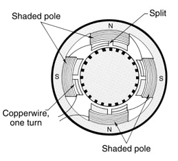
Figure 2 – Rings in shaded-pole motor distort alternating field sufficiently to cause rotation.
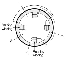
Figure 3 – Split-phase windings in a twopole motor. Starting winding and running winding are 90 � apart.
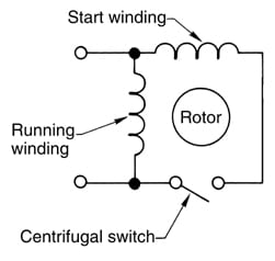
Figure 4 – Split-phase start induction motor.
- Shaded pole motors have a continuous copper loop wound around a small portion of each pole, Figure 2. The loop causes the magnetic field through the ringed portion to lag behind the field in the unringed portion. This produces a slightly rotating field in each pole face sufficient to turn the rotor. As the rotor accelerates, its torque increases and rated speed is reached. Shaded pole motors have low starting torque and are available only in fractional and subfractional horsepower sizes. Slip is about 10%, or more at rated load.
- Split phase motors, Figure 3, use both a starting and running winding. The starting winding is displaced 90 electrical degrees from the running winding. The running winding has many turns of large diameter wire wound in the bottom of the stator slots to get high reactance. Therefore, the current in the starting winding leads the current in the running winding, causing a rotating field. During startup, both windings are connected to the line, Figure 7. As the motor comes up to speed (at about 25% of full-load speed), a centrifugal switch actuated by the rotor, or an electronic switch, disconnects the starting winding. Split phase motors are considered low or moderate starting torque motors and are limited to about 1/3 hp.
- Capacitor-start motors are similar to split phase motors. The main difference is that a capacitor is placed in series with the auxiliary winding, Figure 4. This type of motor produces greater locked rotor and accelerating torque per ampere than does the split phase motor. Sizes range from fractional to 10 hp at 900 to 3600 rpm.
- Split-capacitor motors also have an auxiliary winding with a capacitor, but they remain continuously energized and aid in producing a higher power factor than other capacitor designs. This makes them well suited to variable speed applications.
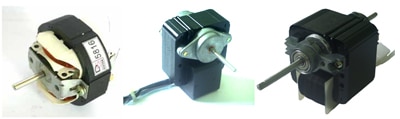
Sinotech Induction Motors are engineered in the U.S. and manufactured in China, Taiwan and Korea.