The value in the ( ) is the value for the small gear shaft motor
Characteristics of Motors Used In Gearmotors
| Model |
Out- put |
Volt | Freq | Poles | Duty | Rated | Start torq |
Capaci- tance |
|||
| Motor | Motor with gear shaft | Spd | Curr | Torq | |||||||
| W | V | Hz | P | rpm | A | N.m | N.m | μF/VAC | |||
|
5RK120A-AMF brake motor |
5RK120GU-AMF brake motor w/gear shaft |
120 |
1ph110 |
50 | 4 | 30Min | 1300 | 2.10 | 0.90 | 0.78 | 30.0/250 |
| 5RK120A-CMF brake motor | 5RK120GU-CMF
brake motor w/gear shaft |
120 | 1ph220 | 50 | 4 | 30Min | 1300 | 0.92 | 0.87 | 0.75 | 7.0/450 |
|
5RK120A-SMF brake motor |
5RK120GU-SMF brake motor w/gear shaft |
120 | 3ph220 | 50 | 4 | 30Min | 1300 | 0.86 | 0.87 | 3.00 | / |
|
5RK120A-S3MF brake motor |
5RK120-S3MF brake motor w/gear shaft |
120 | 3ph380 | 50 | 4 | 30Min | 1300 | 0.51 | 0.87 | 3.00 | / |
The required capacitor value will vary depending on operating voltage. A correct capacitor is required to match the applied voltage.
General Motor Characteristics
Insulation Resistance: 100M at 500V between motor winding and shell
Insulation Voltage:1500V 50/60Hz @1min between motor winding and shell
Temperature Rise: Max 80oC
Insulation Class: Class B (130oC)
Operating Temperature: -10oC to +40oC (Three phase -10oC to +50oC)
Humidity: 85% max.
Motor Model Code
| 5 | R | K | 60 | GN – | C | F |
|---|---|---|---|---|---|---|
| Model & Dimension | Motor Type | Motor Series | Output Power | Shape of Motor Shaft | Supply & Poles | Other accessory |
| 0: 42mm | I: Induction motor | K Series | 1: 1W | A: Flat type | A: 1 110V 50Hz 4P | F: Fan |
| 2: 60mm | R: Reversible motor | 3: 3W | A1: Milled keyway | B: 1 110V 50Hz 2P | FF: Forced Fan | |
| 3: 70mm | T: Torque motor | 6: 6W | GN: General Helical Gear | C: 1 220V 50Hz 4P | M: Mag Brake | |
| 4: 80mm | 15: 15W | GU: Reinforced Helical Gear | D:1 220V 50Hz2P | P: Overheat Protector | ||
| 5: 90mm | 25: 25W | E: 1 110V 60Hz 4P | T: Terminal Box | |||
| 6: 100mm | 40: 40W | G: 1 110V 60Hz 2P | ||||
| 60: 60W | H: 1 220V 60Hz 4P | |||||
| 90: 90W | J: 1 220V 60Hz 2P | |||||
| 120: 120W | S: 3 220V 50Hz 4P | |||||
| 140: 140W | S3: 3 380V 50Hz 2P | |||||
| T: 3 220V 50Hz 2P | ||||||
| T3: 3 220V 50Hz 2P | ||||||
| L: 3 220V 60Hz4P | ||||||
| M: 3 380V 60Hz 4P | ||||||
| N: 3 220V 60Hz 2P | ||||||
| Q: 3 380V 60Hz 2P |
Gearbox Code
| 5 | GN | 50 | K |
|---|---|---|---|
| Model & Dimensions | Gear Type | Reduction Ratio | Bearing Type |
| 0: 42mm | GN: General Helical Gear | Example: 50:1 Reduction Ratio | K: Ball Bearing |
| 2: 60mm | GU: Reinforced Helical Gear | KB: Ball Bearing For Type GU Square Case | |
| 3: 70mm | B: Grease Bearing | ||
| 4: 80mm | |||
| 5: 90mm | |||
| 6: 100mm |
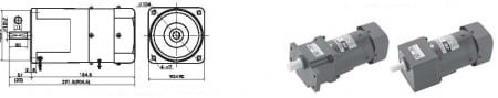
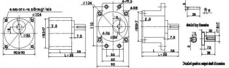
Overall Dimensions of Gearbox for Gearmotors
| Gear ratio | Length (mm) | Wt. (kg) | |
| Gearbox for gearmotor | 3-9 | 65 | 1.21 |
| 10-18 | 1.30 | ||
| 20-75 | 1.40 | ||
| 90-200 | 1.45 | ||
| Motor w/o gearbox | 4.18 | ||
Allowable Torque on Gearbox for Gearmotors
| Freq. | Reduction factor | 3 | 3.6 | 5 | 6 | 7.5 | 9 | 10 | 12.5 | 15 | 18 | 20 | 25 | |
| 50Hz | Output shaft spd | rpm | 500 | 417 | 300 | 250 | 200 | 166 | 150 | 120 | 100 | 83 | 75 | 60 |
| Allowable torque | N.m | 2.14 | 2.57 | 3.57 | 4.29 | 5.38 | 6.43 | 6.43 | 8.05 | 9.66 | 11.6 | 11.6 | 14.6 | |
| 60Hz | Output shaft spd | rpm | 600 | 500 | 360 | 300 | 240 | 200 | 180 | 144 | 120 | 100 | 90 | 72 |
| Allowable torque | N.m | 1.80 | 2.16 | 3.00 | 3.60 | 4.49 | 5.39 | 5.39 | 6.75 | 8.10 | 9.72 | 9.72 | 12.2 |
| Freq. | Reduction factor | 30 | 36 | 40 | 50 | 60 | 75 | 90 | 100 | 120 | 150 | 180 | 200 | |
| 50Hz | Output shaft spd | rpm | 50 | 41 | 37 | 30 | 25 | 20 | 16 | 15 | 12 | 10 | 8 | 7.5 |
| Allowable torque | N.m | 17.5 | 19.6 | 19.6 | 19.6 | 19.6 | 19.6 | 19.6 | 19.6 | 19.6 | 19.6 | 19.6 | 19.6 | |
| 60Hz | Output shaft spd | rpm | 60 | 50 | 45 | 36 | 30 | 24 | 20 | 18 | 15 | 12 | 10 | 9 |
| Allowable torque | N.m | 14.6 | 17.6 | 19.5 | 19.6 | 19.6 | 19.6 | 19.6 | 19.6 | 19.6 | 19.6 | 19.6 | 19.6 |
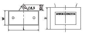
Capacitor for Gearmotors
|
Capacitance μF ±5% |
Voltage | L | W | H |
| V | mm | mm | mm | |
| 7.0 | 450 | 47 | 26 | 38 |
| 30.0 | 250 | 68 | 32 | 56 |
Wiring Diagram for Gearmotors
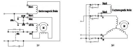
Motors described above are typical and can be customized upon request.