This page is a tutorial on using encoders. First, a brief overview of the hardware so we all understand what is going on, then into algorithms and software to read the encoders.
While encoders can be constructed with other sensing mechanisms, like mechanical or magnetic; we’ll discuss the optical encoder as an example.
Encoders may measure other motions than rotary motion (e.g. linear), we will use a rotary encoder for an example as that is what you will probably be most likely to use to measure wheel rotation.
There are two basic kinds of encoder information: absolute and relative. Absolute provides a code which tells you the exact position of the wheel. Incremental encoders just measure how far the wheel has moved. Incremental encoders are used for measuring robot wheel travel.
Two examples of the innards of an incremental optical rotary encoder are shown above. In each case, a light beam is emitted and sensed by a photo detector. In the left picture, the light beam passes through slots in the sensing wheel; in the right picture, the light beam reflects from light and dark portions of the sensing wheel providing strong and weak reflections. Circuitry, either within the encoder package itself or supplied by you, will take the signal sensed by the photo detector and turn it into a nice 0 to 5 vdc signal suitable for interfacing to your processor.
The picture on the right shows how the photo detector sees the light and dark lines (or holes)  and what the resulting voltage is. The light and dark horizontal strips represents the bars (or holes) on the rotary encoder strip. Whenever a light strip is in front of the detector, the output voltage switches to high (5 vdc). Whenever a dark strip is in front, the voltage is low (0 vdc).
Your processor can read these pulses and count them (by various methods to be described later). By knowing how many pulses are detected per wheel revolution, and the circumference of your wheel, you can calculate how far the robot has moved. Usually. But, there is one deficiency with this simple encoder. The processor will receive pulses that look the same whether the wheel is turning forward or reverse. Hence, the processor doesn’t know whether to add or subtract the pulses from the distance traveled without some additional information. Your software may be able to ASSUME which direction the wheel is turning (i.e. if the motor is being commanded forward, then probably the encoder pulses are counting forward), but using a more sophisticated encoder solves the problem directly.
A “quadrature” encoder has one additional detector. Note that in the drawing below, detector A is pointed at the start of a white sector and detector B is pointed to the center of a black sector. This offset provides the additional information.
If the black/white strip is passing from right to left (moving left), the processor will get a pulse to count from detector A as it reaches the beginning of a white strip (in the position shown). At that time, detector B is looking at a black strip and is putting out a 0 logic signal. Using your imagination (since I don’t want to redraw the picture), if the black/white strip is moving to the right instead, when the A detector encounters the beginning of a white strip, detector B will be in the middle of a white strip. Hence, the direction of motion when detector A gets a pulse can be determined by looking at the status of detector B. Note that if your are building your own quadrature encoder, the A and B detectors don’t have to be measuring the same light strip (that is, right next to each other), they can be located anywhere around the wheel as long as they have the same offset of one half the width of a black or white strip.
You may find an occasional encoder with 5 wires (one ground, one power, two signals for the A & B detectors, and a fifth wire called the Index. This signal provides a pulse when the encoder is oriented in one specific direction. This permits you to use an incremental in a manner similar to an absolute encoder; by rotating the encoder until the index mark is detected then counting incremental pulses away from the index.
So, how do you determine distance in software?
First, you have to detect the pulses. Two common methods exist to read a pulsing signal to a processor. Polling and interrupts. It is POSSIBLE to count the pulses doing polling. If your software continuously samples an input pin with the detector signal on it, it can increment a counter when that signal changes state. HOWEVER, it is difficult to do anything else with your software while you are doing this polling because a pulse may be missed while the software is off doing something like navigation or controlling the motors. And, as your encoder system becomes more precise (more counts per revolution or adding quadrature detection or the robot starts moving more rapidly (faster pulses)), it becomes more difficult to get anything else done since more time must be spent polling. And, while I MAY sound a little negative about this, some people have built robots which are capable of reading encoders through polling and performing other tasks and winning contests even.
However, there is a better way. Many processors have interrupt capabilities. An interrupt is a hardware/software device which causes a software function to occur when something happens in hardware. Specifically, whenever the detector A pulse goes high, the processor can be interrupted such that it suspends its ongoing navigation or motor control task, runs a special software routine (called an interrupt handler) which can compute the new distance traveled. When the interrupt handler is done, the processor automatically returns to the task it was working on when the interrupt occurred. Sounds much easier, doesn’t it? Actually, it takes more software to set it up, but it just does the job SO much better.
We’ll get to some code examples in a bit, but first let’s look at the logic which can be used to read the encoders.
With one detector:
When leading edge of pulse occurs:
- IF (motor command is forward) THEN distance = distance + 1
- IF (motor command is reverse) THEN distance = distance – 1
Note that if the motor command is not forward or reverse, distance is not changed. This avoids the possible problem of the robot stopping where the detector is right on the edge of a white strip and might be tripping on and off with no real motion.
Another problem is that if the motor is rolling along and is commanded to zero, it might coast a little before stopping. The pseudo code above would miss the pulses that occur during coasting. One way to minimize this problem is to slowly decelerate to a stop so there is little or no coasting after the motor is set to zero.
With two detectors (quadrature):
When leading edge of pulse occurs:
- IF (detector B is high) THEN distance = distance + 1
- IF (detector B is low) THEN distance = distance – 1
This logic will count all wheel motion properly. Even coasting after motor shutdown, and even if the motor is commanding reverse and the wheel happens to be going forward (probably more coasting). The problem of stopping on the edge of a white sector still exists. I haven’t found it to be a problem, but it could be that the encoders I use take care of it with some hysteresis.
Improved resolution:
The reflective sample encoder in the first picture on this page (right side) has 16 white sectors per revolution. The counting schemes described so far count only transitions to a white sector so 16 counts per revolution is the best they can do. Some processors (including my favorite the Motorola types like HC11 and HC12 series) can generate interrupts both when a signal goes high OR when it goes low OR for both high and low transitions. This says that we can double the resolution of the encoder by counting both transitions.
This could be handled by two separate interrupts:
When leading edge of pulse occurs: (transition to high interrupt)
- IF (detector B is high) THEN distance = distance + 1
- IF (detector B is low) THEN distance = distance – 1
When trailing edge of pulse occurs: (transition to low interrupt)
- IF (detector B is low) THEN distance = distance + 1
- IF (detector B is high) THEN distance = distance – 1
Or by a single interrupt if it can be generated by either transition:
When leading or trailing edge of pulse occurs: (transition to high or low interrupt)
- IF (detector A is high AND detector B is high) THEN distance = distance + 1
- IF (detector A is high AND detector B is low) THEN distance = distance – 1
- IF (detector A is low AND detector B is low) THEN distance = distance + 1
- IF (detector A is low AND detector B is high) THEN distance = distance – 1
(I’m sure you can find more concise ways of coding this!!)
The ultimate:
Now, if you were able to do interrupts on both high and low transitions, it is possible to add one (or two) more interrupts based on detector B (which switches half way between the detector A pulses) which will give double the distance resolution again. I’ll leave it to you to figure out the additional code required.
Hardware:
All these improved schemes aren’t free (except for the software).
The simplest pulse counter takes just one input pin (with interrupt capability) per encoder.
Adding quadrature for direction adds one more pin (no interrupt required).
Doubling the resolution by reading high and low transitions will require one more pin. Either another interrupt pin if you can’t read high and low on the same pin), or another pin to read the status of the detector A signal.
And doubling the resolution again may require one or two more interrupt pins depending on whether you can read high and low on the same pin.
Of course, if you are reading the detectors by polling, I guess you can do it all with just two input pins.
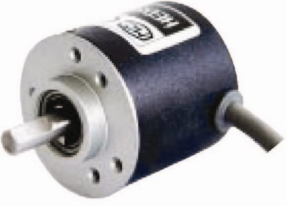 Sinotech can ensure excellent Optical Encoders from China, Taiwan and Korea and is very price competitive. Sinotech is dedicated to delivering optical encoders from China, Taiwan and Korea to you at lower prices but the same quality, service and terms as a domestic supplier.
Sinotech Optical Encoders are engineered in the U.S. and manufactured in China, Taiwan and Korea.